See the protobuf definitions in the synapse-api repo for the most complete reference.
| Node | Dataflow |
|---|---|
| Electrical Broadband | Source |
| Electrical Stimulation | Sink |
| Optical Broadband | Source |
| Optical Stimulation | Sink |
| Spectral Filter | Interstitial |
| Spike Detect | Interstitial |
| Synapse Application | App |
| Disk Writer | Interstitial |
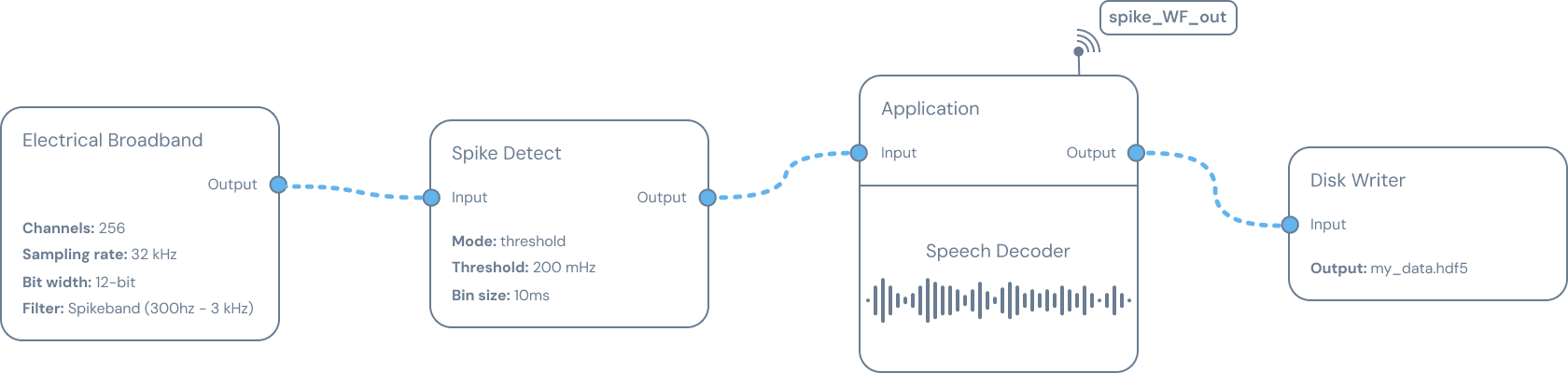
Electrical Broadband
Outputs broadband electrophysiology data from electrodes as a collection of channels with the same data rate. Electrical Broadband nodes are often paired with a Spectral Filter node followed by a Spike Detect node to downsample the signal to a more manageable size for streaming purposes.
| Config | Description |
|---|---|
| peripheral_id | The ID of the peripheral that supports the node. |
| channels | A list of channels with a message containing the channel ID, the measuring electrode ID, and the reference electrode ID. |
| bit_width | The number of bits to represent the broadband measurement. |
| sample_rate | The number of samples per second in Hz. |
| gain | Multiplies the amplitude of the inputted signal by the set value. |
| low_cutoff_hz | Attenuates the amplitude of any signals below set frequency. |
| high_cutoff_hz | Attenuates the amplitude of any signals above set frequency. |
Electrical Stimulation
Accepts input data to stimulate through electrodes.
| Config | Description |
|---|---|
| peripheral_id | The ID of the peripheral that supports the node. |
| channels | A list of channels with a message containing the channel ID, the measuring electrode ID, and the reference electrode ID. |
| bit_width | The number of bits to represent the broadband measurement. |
| sample_rate | The number of samples per second in Hz. |
| lsb | Translates the signal into voltage in µV/unit. |
Optical Broadband
Outputs broadband optical data from photodiodes as a collection of channels with the same data rate.
| Config | Description |
|---|---|
| peripheral_id | The ID of the peripheral that supports the node. |
| pixel_mask | A list of IDs of active pixels. |
| bit_width | The number of bits to represent the broadband measurement. |
| frame_rate | The number of samples per second in Hz. |
| gain | Multiplies the amplitude of the inputted signal by the set value. |
Optical Stimulation
Accepts input data to stimulate through LEDs.
| Config | Description |
|---|---|
| peripheral_id | The ID of the peripheral that supports the node. |
| pixel_mask | A list of IDs of active pixels. |
| bit_width | The number of bits to represent the broadband measurement. |
| frame_rate | The number of samples per second in Hz. |
| gain | Multiplies the amplitude of the inputted signal by the set value. |
Spectral Filter
Accepts an input and applies a basic frequency-domain filter.
| Config | Description |
|---|---|
| method | Low: Reduces the amplitude of any signal below the low_cutoff_hz frequency to zero. |
| High: Reduces the amplitude of any signal above the high_cutoff_hz frequency to zero. | |
| Bandpass: Reduces the amplitude of any signal outside the range of low_cutoff_hz to high_cutoff_hz frequency to zero. | |
| Bandstop: Reduces the amplitude of any signal inside the range of low_cutoff_hz to high_cutoff_hz frequency to zero. | |
| low_cutoff_hz | Lower frequency threshold in Hz. |
| high_cutoff_hz | Higher frequency threshold in Hz. |
Spike Detect
Accepts broadband neural data and detects action potentials (neural spikes) using a spike thresholding algorithm. Outputs binned spike data, where bin size (in milliseconds) is set using bin_size_ms.
| Config | Description |
|---|---|
| mode | Threshold: Counts the number of times the absolute value of the input data crosses a set threshold value within a set time period. Threshold and bin size are user defined. Threshold mode assumes a ~1 ms refractory period between spikes. |
| threshold_uV | The cutoff value in µV that determines when the node classifies the signal as a spike. |
| bin_size_ms | The length of time in ms before the spike count resets. |
Synapse Application
The application node is used to implement user-defined algorithms or models and accepts input from other nodes in the signal chain. Data is output using Taps API and is application-specific. See the Synapse App SDK for more information about developing your own Synapse App.
| Config | Description |
|---|---|
| data input | Neural data read in from other nodes in the signal chain (e.g., broadband, spectral filter, binned spikes). |
| data output | Arbitrary output defined by the app. |
Disk Writer
The Disk Writer node saves broadband frame data to on-device storage. Data is saved in an HDF5 file with the .h5 extension. The Disk Writer node can ingest data from any node outputting data using the broadband frame format. Data attributes are preserved as they were output. For example, a Disk Writer node connected to the output of Electrical Broadband saves unfiltered electrical broadband data, whereas one connected to a Spectral Filter saves filtered data. A Disk Writer should be placed at the end of a signal chain or on a branch from an intermediate node.
Multiple Disk Writer nodes can operate simultaneously to save output from more than one node. Each Disk Writer creates a separate data file and should have a unique name. The HDF5 output facilitates interoperability with the Neurodata Without Borders format.
| Config | Description |
|---|---|
| filename | The recording name. Supply a base name without a parent path or extension. |
| storage_device_id | The Storage Device on which to create the recording. |
HDF5 Format
The Disk Writer creates a recording directory under data/disk_writer on the selected Storage Device:
/data/disk_writer/<recording-name>/
├── config.json
└── <recording-name>.h5
config.json contains the complete signal-chain configuration. If the requested directory or file already exists, the device adds a numeric suffix. Stopping and restarting the same configured Disk Writer creates a new .h5 file rather than appending to the previous file.
The HDF5 layout is inspired by NWB organization, but it is a Synapse recording format rather than a complete NWB file.
Dataset layout
| Path | Type | Length | Meaning |
|---|---|---|---|
/acquisition/ElectricalSeries | int16 | Total values across all frames | ADC counts from each BroadbandFrame.frame_data, flattened in frame order. |
/acquisition/timestamp_ns | uint64 | One value per frame | Monotonic sampling timestamp reported by the frame. |
/acquisition/unix_timestamp_ns | uint64 | One value per frame | The frame's device-reported steady-clock timestamp. |
/acquisition/sequence_number | uint64 | One value per frame | Monotonically increasing frame sequence number. Gaps indicate missing frames. |
/acquisition/channel_range_type | uint32 | One value per channel range | Numeric ChannelType for a contiguous range, such as electrode or GPIO. |
/acquisition/channel_range_count | uint32 | One value per channel range | Number of values in the corresponding range. |
/acquisition/channel_range_start | uint32 | One value per channel range | Absolute start index of the range in the flattened ElectricalSeries dataset. |
/general/extracellular_ephys/electrodes/id | uint32 | One value per configured input channel | Channel IDs in the order supplied to the Disk Writer. |
All datasets are one-dimensional, chunked, and extendable.
Frame and channel order
ElectricalSeries is intentionally stored as a flat one-dimensional array, so the file itself has no row-major or column-major setting. The writer appends complete frames in order:
frame 0: channel 0, channel 1, ... channel C-1
frame 1: channel 0, channel 1, ... channel C-1
...
Conceptually, the data is frame-major: time advances by row and channel position advances by column. For frames with a constant width, reshape the flat array to (number_of_frames, values_per_frame) using C/row-major order:
import h5py
import numpy as np

with h5py.File("recording.h5", "r") as file:
    counts = file["/acquisition/ElectricalSeries"][:]
    timestamps_ns = file["/acquisition/timestamp_ns"][:]
    sequence_numbers = file["/acquisition/sequence_number"][:]

    frame_count = len(timestamps_ns)
    if frame_count == 0 or counts.size % frame_count != 0:
        raise ValueError("Recording does not contain constant-width frames")

    values_per_frame = counts.size // frame_count
    frames = counts.reshape((frame_count, values_per_frame), order="C")
    microvolts = frames.astype(np.float32) * file.attrs["lsb_uv"]
frames[i, j] is value j from frame i. A frame normally holds one sample per enabled channel, all electrodes. A source may also place non-electrode values, such as GPIO samples, in the same frame; the channel-range datasets identify which columns are which. channel_range_type holds the numeric ChannelType (0 electrode, 1 GPIO), channel_range_count its width, and channel_range_start its absolute offset into ElectricalSeries. Every frame contributes its own entries, so read the first frame's to learn a constant-width layout.
Scale only the electrode columns by lsb_uv; GPIO values are digital states. When the channel-range datasets are empty, every value is an electrode sample.
File attributes
| Attribute | Location | Type | Meaning |
|---|---|---|---|
sample_rate_hz | File root | float | Sample rate of the Disk Writer input. |
lsb_uv | File root | float | Microvolts represented by one ADC count. |
session_description | File root | String | Recording filename without the .h5 extension. |
session_start_time | File root | String | ISO 8601 time at which the file was initialized. |
electrode_mapping | File root | Compound array, when available | Mapping records containing electrode_id, reference_id, user_id, index_in_frame, and channel type. |
device_type | /general/device | String | Device family; currently written as SciFi. |
To convert an ADC count to microvolts:
voltage_uv = adc_count * lsb_uvThe timestamps, sequence numbers, and data rows have the same frame order. Compare adjacent sequence numbers to detect dropped frames, and use timestamp_ns rather than array position when exact timing matters.